This article aims to vulgarize the technology of Energy Recovery Ventilation system (ERV) using a total heat exchanger. In a first part, thermal comfort in building are presented. Then principles and technology aspects are explained. In a last part, specific efficiencies to rate this kind of appliance are defined. Development of Total Heat Exchanger is part of ADAPTIWALL project (“Multi-functional light-weight WALL panel based on ADAPTive Insulation and nanomaterials for energy efficient buildings “, www.adaptiwall.eu)
Context & Thermal comfort
Considering, acceptable conditions of Humans living in buildings, HVAC systems can be introduced. HVAC means, heating, ventilating, and air conditioning. The goal of HVAC systems in buildings is to provide good, healthy comfort and air quality for occupants, considering a wide range of outdoor conditions.
Notion of thermal comfort is defined as the state of mind in humans that expresses satisfaction with the surrounding environment (ANSI/ASHRAE 2003). These temperature and hygrometry conditions are a function of each person, of external climate condition, but they can be approximated by the windows presented in the following psychometric graph.
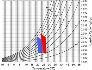
Figure 1: ASHRAE (1) comfort zone representation (blue in winter, red in summer).
Other classifications of thermal comfort exist, Canadian Humidex and American Heat Index, and give a classification of human-perceived equivalent temperature, in function of a couple of values of temperature and hygrometry (respectively dew point temperature or relative humidity).
Today, HVAC systems are required to be more energy efficient, while considering the ever-increasing demand for better indoor air quality, performance and environmental issues. There are many studies to improve the HVAC systems in buildings while reducing the energy costs and environmental impacts. Energy recovery systems take a large part of this axis of research. In most industrialized countries, energy consumption by the HVAC sector accounts sometimes for 1/3 of the total energy consumption of the whole society. It highlights the huge energy saving potential for this domain, the technology of Energy Recovery Ventilation system (ERV) using a total heat exchanger is a strong way to exploit this one.
Total Heat Exchanger (THEX) in Energy Recovery Ventilation (ERV) system
In the context of ventilation, energy recovery system and thermal comfort in building, energy could be recovered from the exhaust air flux to the fresh air flux. Enthalpy exchangers or total heat exchanger (THEX) integrated in an Energy Recovery Ventilation system could save a large fraction of energy for heating/cooling and humidifying/dehumidifying.
Total heat exchanger is a way to recover energy simultaneously both for temperature (sensible heat) and hygrometry (latent heat). The walls of “plate and fin” type exchangers are specific membranes named
imper-respirant. This means; these membranes are permeable to moisture but tight to air molecules (di-oxygen and di-nitrogen) and liquid water. The rate of moisture transferred from one to the other air flow is driven by the hygrometric gradient between the two fluids (water vapor partial pressure or moisture concentration in dry air) and diffusive properties of membrane. Sensible heat is also transferred through membrane from the hottest to coldest fluid. The following picture describes principle of this technology.
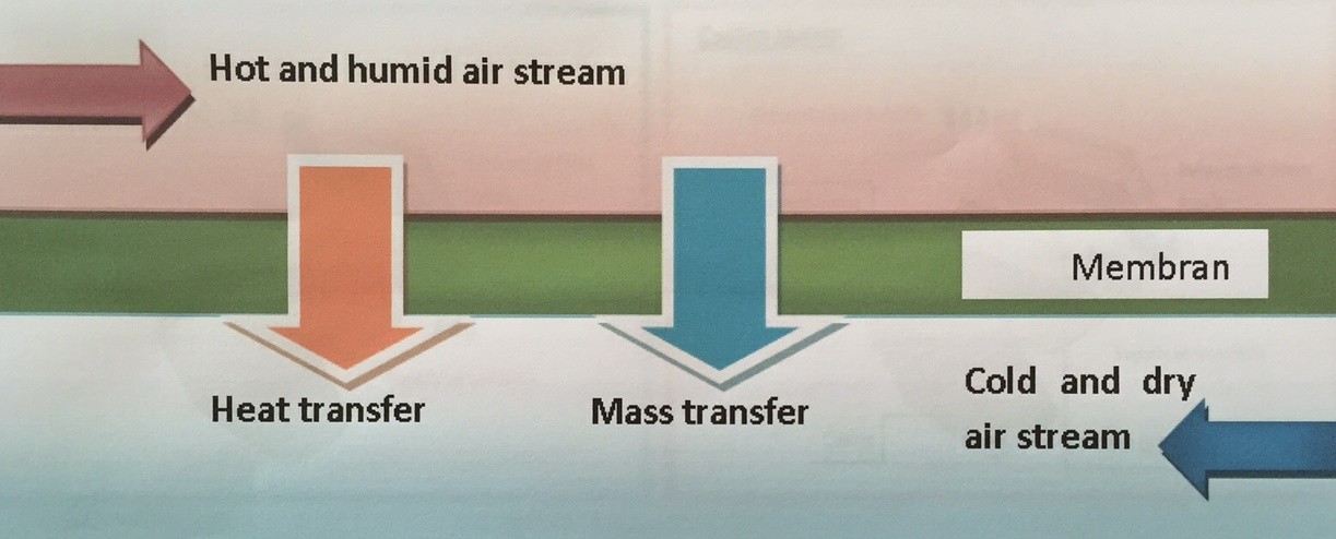 Figure 2: Principle of total heat exchange through an imper-respirant membrane of a kind of this appliance.
In summer, fresh air (outside air) is warmer and more humid than exhaust air, so fresh air is precooled and dehumidified due to gradients of temperature and moisture concentration. On the contrary, in winter, humidity and sensible heat are recovered from exhaust air and allow saving a large part of fresh air heating energy, and improving thermal comfort by humidifying the insufflated air. With total heat exchangers, energy consumption is largely recovered and the efficiency of the existing HVAC systems can also be improved. The following picture illustrates this seasonal behavior.
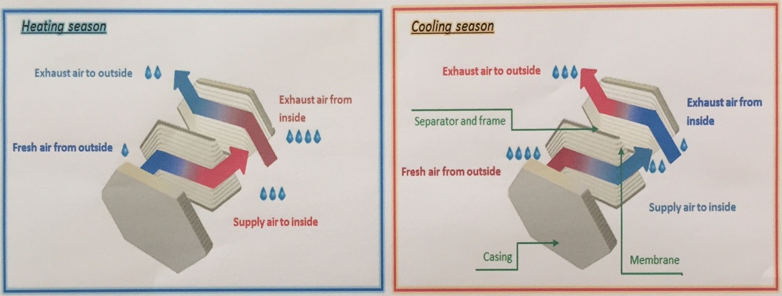 Figure 3: Illustration of coupled mass and thermal transfers and seasonal behavior.
To highlight all benefits brought by this technology in terms of heat recovery and improvement of thermal comfort, an example of enthalpy exchange is given on a simplified psychometrics diagram for winter and summer conditions.
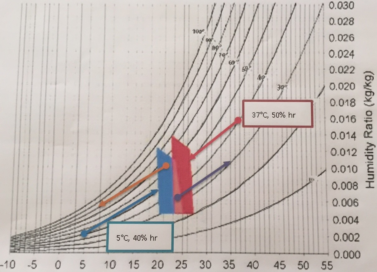 Figure 4: Psychometric diagram with summer and winter behavior examples.
Adding on this example, the same case with a dual flow heat exchanger (only sensible energy exchange) is presented.
Example of a next figure is given for equal flow rate of fresh and exhaust air in heat exchanger, and for the following inside and outside winter air conditions:
- Inside : T= 20°C, RH= 50%
- Outside : T= 0°C, RH= 80%
/Blue area is the comfort zone for winter conditions. Green line is evolution of exhaust air in dual flow heat exchanger. Orange line is evolution of exhaust air in total heat exchanger. Violet line is evolution of fresh air in dual flow heat exchanger. Blue line is evolution of fresh in total heat exchanger. Red lines are evolution of air treatment to add after the passage of fresh air in recovery (dual flow or total) heat exchanger, there remains a need to heat and to humidify./
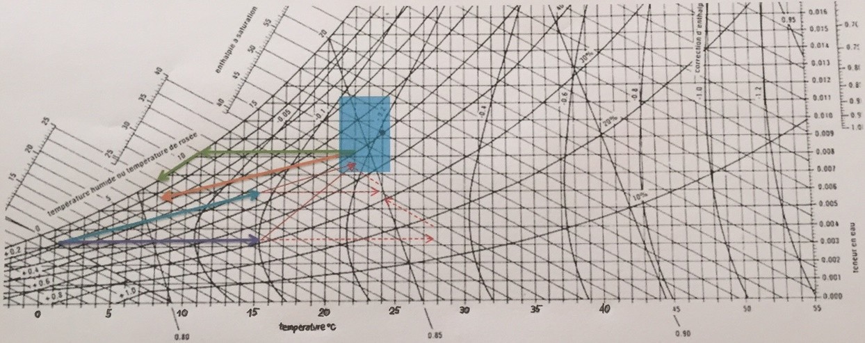 Figure 5: Example of enthalpy evolution on psychometric diagram for total heat exchanger and dual flow heat exchanger.
Comparison of the two kinds of appliance leads to understand the following points:
- With the dual flow heat exchanger, fresh air is only preheated, there is no recovery of moisture between exhaust air and fresh air, whereas with THEX, fresh cold and dry air is preheated and humidified.
- It is obvious that fresh air post treatment in the case of dual flow heat exchange, if temperature and hygrometry of the air inside the room have to be reached, will be much larger energetically speaking than in the case of THEX. See the red lines evolutions on the psychometric diagram.
- Especially in winter conditions, there is a large occurrence of condensation (and freezing if T<0°C) on the outside of exhaust air side of dual flow heat exchanger. Although this also occurs with the THEX, its probability is much smaller than the case with dual flow configuration. Indeed, the decreasing of moisture content in exhaust air leads to a simultaneous decrease of the dew point temperature at the same dry temperature at the outside of the exhaust air side. Furthermore, this kind of condensation (and freezing if T<0°C) occurrence has to be avoided in a THEX configuration, because firstly, the potential damages on the membrane are largely increasing, and secondly, the creation of local mass and thermal transfer resistances are responsible for decreasing efficiencies. By-pass solution is then manage.
This comparison can also be done for summer climate conditions, THEX will give a larger degree of freedom in comparison with a dual flow heat exchanger considering condensation occurrence. But, the summer cases with a high relative humidity in the outside fresh air have to be examined carefully, it will require an adequate control strategy using bypass management.
Technology Aspects
Technology of enthalpy heat exchanger is completely different from enthalpy wheel, usually used in HVAC global system. No desiccant materials are involved in this kind of heat exchanger. In a few words, is composed of a stacking of, alternatively, a flow of fresh air and a flow of exhaust air, separated by an imper-respirant membrane. Generally to maintain each volume of the stacking together, a separator is setup, it is for example a corrugated sheet of aluminum or of polymer. A frame all around the stacking gives mechanical stability and inter-channel tightness. The pictures below show the state of the art for this kind of assemblage and how is it configured in an HVAC process.
- Total heat exchanger in a cross flow configuration
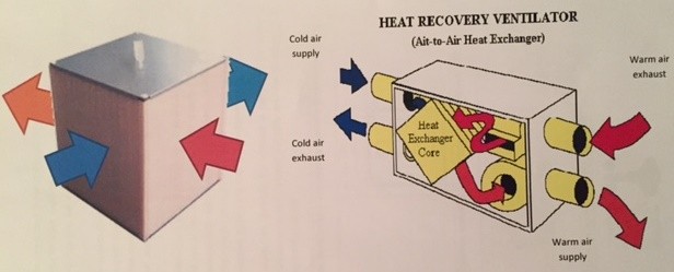
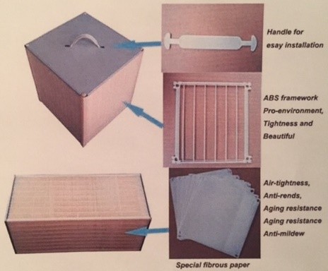
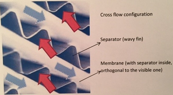
Figure 6: Total heat exchanger technology aspects in a cross flow configuration
- Total heat exchanger in a counter flow configuration
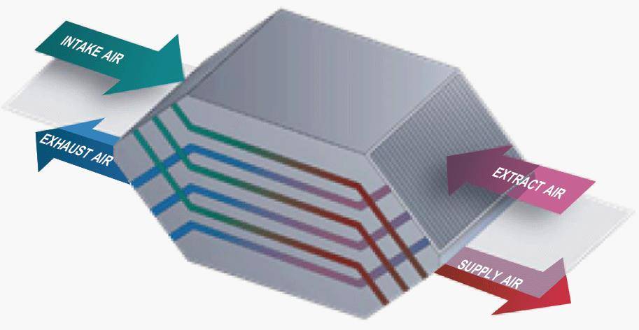
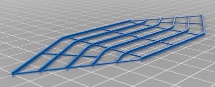


Figure 7: Total heat exchanger technology aspects in a counterflow configuration.
Separator takes a very important place in the design of total heat exchanger. Its main role is to support membrane for each layer of fluid in the stacking. To optimize efficiencies (sensible, latent and enthalpy), separator must do in same time:
- generation of flow “agitation” in the way to improve thermal convection at the membrane but also the intake of moisture by the membrane at the interface with air flow,
- light generation of pressure drop,
- minimization of contact with membrane to keep the largest mass transfer area.
Definition of Efficiencies
When performances of these appliances are studied, different kinds of efficiencies are given:
- Sensible efficiency
- Latent efficiency (or sometimes mass efficiency)
- Enthalpy efficiency
Appliance of the market are in cross and counter flow configuration. Data sheet gives some efficiencies but generally temperature and hygrometry conditions are different. The global performances can be retained.
| Sensible efficiency | Latent efficiency | Enthalpy efficiency |
| 70%-78% | 50%-58% | 55%-60% |
Similar point between these efficiencies is; each time, a quantity of item exchanged between the two fluids is divided by the maximum quantity that can be exchanged between the two fluids.
If the quantity is sensible heat exchanged between the two fluids (Equation 1).
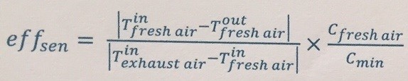 Where
Where
is a temperature in °C; is the calorific flow rate in W/°C
With the mass flow rate in k/s; the specific heat in J/kg.°C
If the quantity is moisture exchanged between the two fluids (Equation 2).
 Where ω is absolute humidity in kg of moisture /kg of dry air.
In this equation, mass flow rate of air is the one defined with dry air.
If the quantity is total energy exchanged between the two fluids (Equation 3).
![]()
Where h is enthalpy of fluid in J/kg
It interesting to note that enthalpy efficiency is not an arithmetic sum of sensible and latent efficiencies, but instead the resultants of two driving transfer forces.
To understand this relation, an example of total heat exchange between two air streams is shown in psychometric diagram, with quantity involved in the determination of efficiencies. See figure on the next page.
Other equations can be defined to estimate efficiencies. The ratio of flow rate (mass or calorific), can be assumed in certain cases to be equal to 1. An alternative is also to consider fresh and exhaust air in same time. To calculate efficiencies of a total heat exchanger, this system of equations is generally used by the scientific community (especially by Zhang). Equation 1,2 and 3 can be rewritten (Equation 4,5,6):
![]()
![]()
![]()
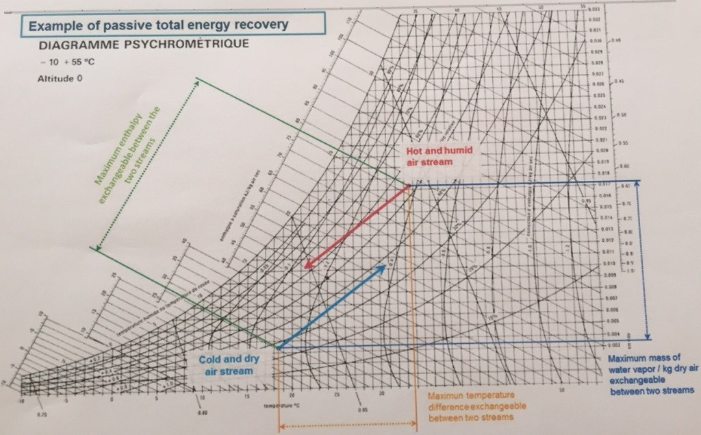 Figure 8: Illustration of maximum enthalpy, temperature and moisture concentration taken in account on calculation of efficiencies.


Speak Your Mind
You must be logged in to post a comment.